1
General
For cryogenic / LNG systems, two phenomena have to be considered in expansion/contraction movement of the piping and insulation.
The first is the contraction and expansion of the materials involved due to the temperature difference between the operational inner surface and the outer surface exposed to the environment. This is considered as thermal expansion/contraction. It has three components: longitudinal, radial and circumferential.
The second phenomenon is due to the movement of the whole piping system during change of operational conditions. In particular at the bends/elbows, this can cause additional mechanical bending expansion/contraction due to the longitudinal thermal expansion.
In cryogenic / LNG services mainly austenitic stainless steel (SS) is used because of its good low temperature characteristics and stable quality. However, due to its large coefficient of linear expansion, such piping require mechanism such as bent piping or bellows to absorb thermal contraction.
The insulation system installed on such piping must be able to absorb that expansion /contraction.
For a proper design and application of the insulation systems the phenomenon of expansion/contraction of the insulation materials must be understood. In CINI 1.3.02a par. 2.3.3 contractions joint are described in general; in this chapter the contraction is explained in more detail.
1
Coefficient of linear expansion
Expansion / contraction of a material is directly related to the temperature difference (ΔT) between ambient temperature and process temperature.
Therefore, the way to calculate the expansion / contraction in the layers of the system shall be done with the following steps:
- Determine the temperature distribution across the insulation system and especially at the interface between the layers. This can either be done approximate with the insulation thicknesses and a linear temperature gradient or by non-linear calculation.
- Then calculate the expansion / contraction of each material at that interface with the temperature difference versus ambient conditions. As the stiffness of the piping is 3-4 decades larger than the insulation material, movement of the piping will be considered as free.
- The following materials are involved in thermal insulation systems in cryogenic services:
| Material | Coefficient of expansion (at 20°C) m/(m.K) | |
| Carbon steel | CS | 12.10-6 |
| Austenitic Stainless Steel | SS | 16.10-6 |
| Invar | Ni36 | 1,7.10-6 |
| Polyisocyanurate | PIR | 70.10-6 |
| Cellular Glass | CG | 9.10-6 |
2
Longitudinal contraction in a PIR insulation system
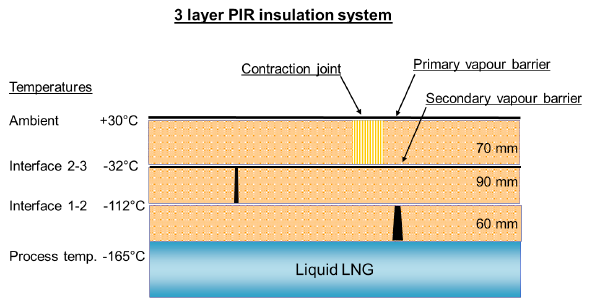
An example calculation is shown to explain the behaviour of the several layers of a PIR insulation system.
2
| Ambient temperature: | +30°C |
| Process temperature: | -165°C |
| Insulation system, consisting of pre-formed PIR sections: | total thickness : 220 mm; |
| Layering in accordance with CINI 10.2.10: | inside > outside: 60 – 90 – 70 mm |
| Pipe sections length: | 1.000 mm; pipe sections in the 1st and 2nd layer are not glued; the joints will open after cool-down due to contraction of the PIR. |
Pipe supports at 6.000 mm distance; supports are fixed to pipe.
Contraction due to max. temperature difference ΔT = 195 K; the temperature gradient in the insulation system is considered linear.
Contraction per running meter:
2

2
The gaps in the 1st and the 2nd layers are schematically indicated in the sketch.
In the outer layer compression in the PIR material will occur in the upper part of the sections; all joints in the outer layer will be glued, so no open joints.
The compressive stress resulting from σcompr= Ecompr x εcompr is below the max. allowable compressive strength of the PIR ( i.e. 16000 kPa x 0,00312 = 50 kPa vs 200 kPa) and so in theory no contraction joint is required.
However, it is common practice to apply a contraction joint in the outer layer of a PIR insulation system. In the above mentioned example, on a 6 meter pipe, the compression joint would need to compensate 6 x 3.12mm = 18,72mm. At a given compaction rate of max. 50%, the contraction joint would need to be 40mm wide minimum. Filling of a contraction joint needs to be loose to allow for the compaction as opposed to an expansion joint, where the filling needs to be pre-compacted to allow for expansion.
In the installation instructions, CINI 1.3.53 par. 2.1.12, a table indicate the maximum length of a PIR insulation system without a contraction joint.
Location of the contraction joint in a PIR system
Location of the contraction joint
2
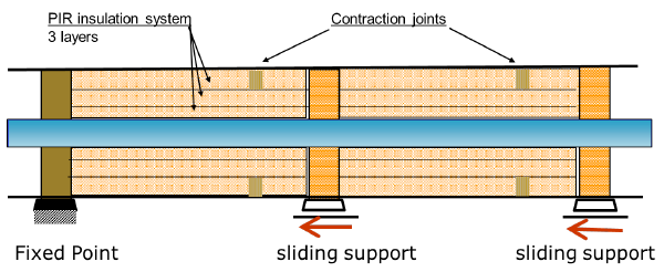
At cool down, the pipe will contract in the direction of the fixed point. The sliding supports are fixed to the pipe and will move towards the fixed point. As a result, the sliding support will put pressure on the pipe insulation sections. As calculated under par.2, the inner sections will contract more than the pipe, but at the out layer, there is no contraction, only pressure from the support. The pressure will be the most at the sliding support side and will be gradually spread and distributed over the PIR cross section in the direction of the fixed point, also due to the friction between the PIR layers.
At the next shut down, the pipe will expand to the original length and the pressure from the sliding support in the PIR outer layer sections will relax. The outer layer sections are glued together and the PIR material only will gradually relax. It is therefore recommended that the first PIR pipe section is glued to the support and at the other end of that first section the contraction joint is located.
In that way the joint near the support remains undamaged and all relaxation is concentrated in the contraction joint at the other end of the pipe section.
At present is specified to install a contraction joint in the middle between two supports.
Based on the above that would not be the correct location and may result in cracks or open joints in the outer layer.
3
Longitudinal contraction in a CG insulation system
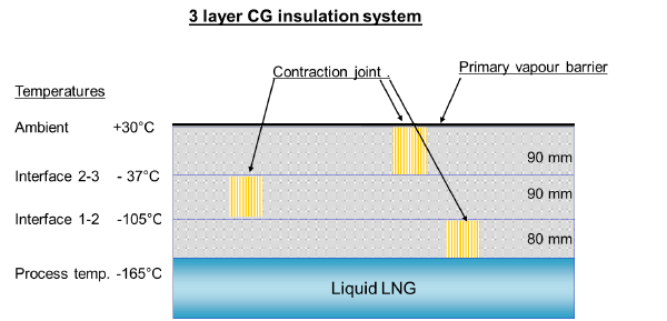
Similar as for the PIR insulation system in par.2 an example calculation will explain the behaviour of the different layers of a CG insulation system.
3
Ambient temperature: +30°C
Process temperature: -165°C
Insulation system, consisting of pre-formed CG sections: total thickness : 260 mm;
Layering in accordance with CINI 10.2.10: inside > outside: 80 – 90 – 90 mm
CG pipe sections length: 600 mm.
Pipe supports at 6.000 mm distance; supports are fixed to pipe.
Contraction due to max. temperature difference ΔT = 195 K; the temperature gradient in the insulation system is considered linear.
Contraction per running meter:

3
In all layers of the CG insulation system compression occurs between the slabs.
The compressive stress resulting from σcompr= Ecompr x εcompr is above the max. allowable compressive strength of the CG (i.e. 800.000 kPA x 0,00136 = 1.088 kPa vs 500 kPa) and so a contraction joint is required. Installing the inner CG slabs with 1-2 mm gaps or the effect of the joints between CG slabs in the outer layer, which are filled and sealed with mastic which can accommodated the compression to a certain extend could in theory make compression joints obsolete. However, it is common practice to install contraction joints in all layers of a CG insulation system.
In the above mentioned example, on a 6 meter pipe, the outer compression joint would need to compensate 6 x 3.12mm = 18,72mm. At a given compaction rate of max. 50%, the contraction joint would need to be 40mm wide minimum.
In case the distance between two supports is 9 m, the contraction difference at the pipe surface is:
| Contraction CG insulation: | 9 m x 9.10-6 x 195 | = | 0,015795 m | = | 15,80 mm | |
| Contraction pipe: | 9 m x 16.10-6 x 195 | = | 0,028080 m | = | 28,08 mm | |
| Difference | -12,28 mm | (compression) |
In that case the total compression at the vapour barrier is 28,08 mm; which require at a given compaction rate of max. 50%, a contraction joint of 60mm wide minimum.
In the installation instructions, CINI 1.3.54 par. 2.1.11, a table indicate the maximum length of a CG insulation system without a contraction joint.
4
Longitudinal contraction in an insulation system on a vertical pipe
As demonstrated in the above example calculations on horizontal piping the gaps between the insulation sections are equally spread over all joints. On vertical piping this is not so much the case. Material loads will make that the lower situated joints are closed and there is a tendency that the complete gap will occur at the highest point; this is below the support or fitting above, where the insulation system is fixed.
The gap may be become so important that the insulation system require the installation of an expansion / contraction joint. In such a case this needs to be placed under the pipe support or under the fitting.
5
Circumferential contraction in a PIR insulation system
5
5
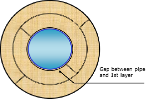
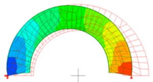
The principle of thermal contraction is the same in the cross-sectional area of the insulation system. The contraction will be highest on the inside of the pipe and almost zero on the outside. For PIR, the inner layers will shrink more than the pipe due to the higher expansion coefficient. Therefore, when prefabricated PIR sections are used with an operating temperature lower than –50°C, the inside diameter of the sections shall be oversized to such an extent that a gap will be formed between the section and the underlying pipe. In the installation instructions of CINI 1.3.53, par. 2.1.11, dimensions of the gaps are shown in relation to the difference in temperatures (ΔT) and the pipe dimensions.
After cooling (“Cool Down”), the pipe diameter and PIR sections will shrink and the entire system will fit tightly.
As there is no superimposing compression coming from the steel pipe, as stated in the longitudinal case, no compression/expansion joints shall be installed in the outer layer circumferential wise. The outer layers will be applied tightly.
6
Circumferential contraction in a CG insulation system
In a CG insulation system, the steel pipe will shrink more that the inner layer of CG. This is due to the lower expansion coefficient of CG. Therefore, the inner layer shall be installed tight without a gap in the inner diameter. Under operational conditions, a small gap will form between the pipe and the CG. This can lead to small free movements.
7
Contraction at an elbow in an insulation system
In long stretches of LNG lines, e.g. loading lines, the contraction of the pipeline is accommodated with expansion loops or bellows (bellows are described in CINI 10.2.11).
The legs of the expansion loops are between 5-13 m. The movement in the expansion loop is considered to be absorbed by the legs through bending. From an insulation point of view the elbows are considered rigid compared to the legs.
Bending of the legs will lead to expansion and contraction in the insulation layers, which superimpose on the thermal expansion / contraction. This needs to be considered when the size of the contraction joint is determined. The exact values shall be calculated by the piping engineer.
As example, the following formula is given for the bending part of expansion if the bending moment or bending force is known:
ε = Rins * M / (E * π * Rpipe3; * T) = Rins * F * L / (E * π * Rpipe3; * T )
| ε | = Strain due to bending |
| E | = Youngs Modulus of pipe |
| Rins | = Radius of insulation Layer |
| Rpipe | = Radius of pipe |
| T | = Wall thickness of pipe |
| M | = Bending moment on the pipe |
| F | = Transverse force on pipe |
| L | = Length of pipe |
In cryogenic insulation systems the elbows are successfully insulated with prefab solid 90° elbows sections with staggered ends at both sides. The prefabricated sections are either segmented and glued or milled, as described in CINI 5.1.14 / 15.
The first pipe section of the outer layer of the adjacent pipe insulation section is glued to the elbow and at the other end the first contraction joint is located.
| * | This chapter will be worked out in more detail, showing the different varieties in cases of pre-insulated pipe sections or prefab solid 90° elbows, the work sequence and the different insulation materials.
These subjects are still under discussion in the CINI Committee “LNG / Cryogenic Thermal Insulation” and the results will be included in the next update. |
